
(5) What's Q | Tips for COIL users(Part-1)
(5) What's Q
The fifth topic is about "Q of coils". This Q may not be so much familiar to those who mainly use power inductors. However, it is one of important parameters in coils for high-frequency application.
What is Q?
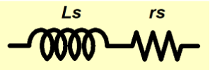
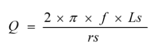
Q is one of parameters that represent difference (amount of loss) from the ideal coils. When the equivalent circuit of coils is as shown in Figure-1, it is calculated in accordance with Formula-1.
Therefore, "Q is high = almost ideal coil which has small loss". When rs = 0, Q = infinite.
In those days, we used to measure Q with a Q meter which was necessity for coil manufacturers. But now we can measure Q with a high performance LCR meter (or impedance analyzer) by setting the circuit mode to "Ls+Q".
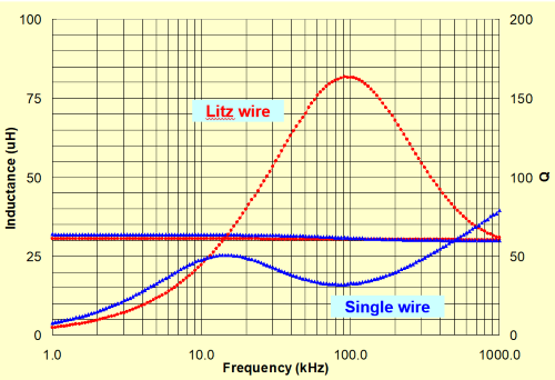
Q value significantly varies depending on the frequency in spite of same coil. Generally, if the frequency gradually changes from lower value, the Q value will reach maximum value at certain frequency. After that, Q will decrease gradually
(characteristic of litz wire in Graph-1 on the next page is the general curve)
Q and ESR
In the capacitors for the power application, not tanδ but the equivalent series resistance (ESR) is often used. In the same way, not Q but DCR is employed for the power inductors.
For the loss, DCR is employed maybe because the resistance is easier for us to understand intuitively than the other factors. Otherwise, DCR is easier to be measured.
Both Q and rs(ESR) are same in meaning, so they can be converted mutually with Formula-1.
Skin effect and litz wire
In two different coils with bigger/smaller DCR, which have a same form, there is the case that Q becomes high on a coil which DCR is bigger when increasing frequency.
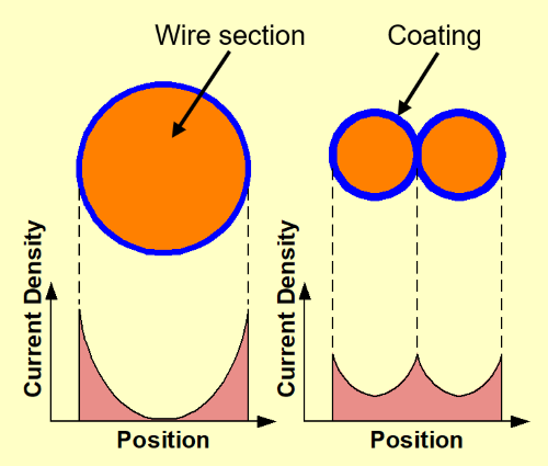
The current flowing through a wire is concentrated on a certain level of depth from the wire surface as Figure-2, when the frequency becomes higher. Then the current is difficult to flow through deeper area. (The thicker a wire is, the larger wasted area is generated at the center that current never flows). It is called skin effect.
This is the method to disperse the concentrated current by using the wire of which the surface area is large though the total cross-section area is small. Actually, individual insulated thin wires are bundled and they are used as single wire (it is called litz wire). The current can flow into the center area of thin wire.
To confirm the actual effect, Graph-1 shows an example of coil characteristics of single wire and litz wire that are wound around same ferrite core.
As you can see from the graph, the litz wire is not almighty and the effective frequency range is limited.
Considering the cost effect, the range of use is also limited.
In the past, the litz wire often had been used to improve Q of the antenna coil for AM radio. However, recently it is rarely used because performance (sensitivity) of semiconductors has been improved.
To heighten Q
Generally, the Q value decreases if there is a metal (conductor) around the coil. It is mainly because an eddy current is generated when the magnetic flux which is generated from the coil passes through the metal. (For eddy current, see later topic.)
In the case of RF inductors, high-Q inductors have been realized by making following efforts:
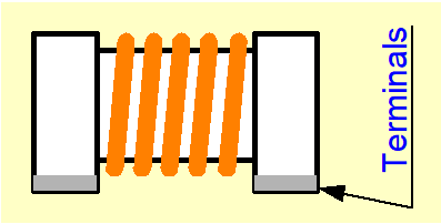
- Keeping windings away from the metal terminals of the coil.
- Keeping windings away from the pattern (copper foil) as far as possible when mounting the coil onto the printed wiring board.
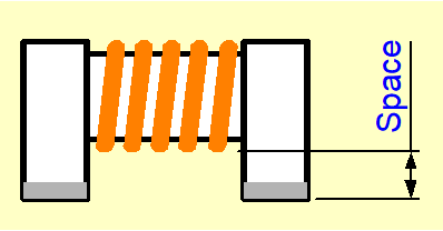
The chip inductors with High-Q (our C2012H) have larger space as shown by Figure-4. As the result, the winding area decreases compared with standard one.
And producible maximum inductance becomes small. However when comparing in the same inductance, higher Q is achieved.
This may be a trivial thing but we are making such continuous efforts to improve the coil characteristics.
Also the open magnetic power inductors may have some effects (not so large as RF inductors), if the printed wiring pattern (copper foil) is just under the coil.
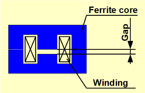
Concerning gap (supplement of third topic)
This is a supplemental description about the gap in third topic.
If the only gap size is changed under the same conditions of ferrite core and windings (see Figure-5), the characteristics are as Graph-2 below.
The relationship between inductance and DC saturation allowable current is mutually dependent.
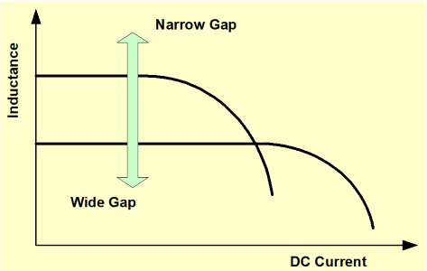
If we want to increase the inductance and the inductor has gap, we can realize that by narrowing the gap without increasing DCR.
However, because of the form (structure), limited type of inductors can change the inductance by changing the gap.
Author
- Some of the products listed in this document are no longer in production.
- As some time has passed since the article was written, the information provided may still contain outdated content.
If you have anything, you can send e-mail by clicking here.
Tips for COIL users Part-1
- (1) Differences between Coil and Inductor
- (2) Main parameters of the inductor
- (3) Inductance of the coil parameters
- (4) Temperature rising of inductor
- (5) What's Q
- (6) Self Resonance Frequency of Inductor
- (7) Open and close magnetic circuitr
- (8) Eddy current & Shield
- (9) Temperature and insulation characteristics
- (10) Operation of coil
- (11) Coupling of coil
- (12) Tips when you use a coil