
(4) Temperature rising of inductor | Tips for COIL users(Part-1)
(4) Temperature rising of inductor
The fourth topic is about "inductors and heat generation". A lot of electronic components have specifications of allowable current value due to the limitation of the heat generation. Coils are subjected to the limitation as well.
What is the problem with heat generation?
First, the heat generation deteriorates the resin coating of wire which is used for coils, and increases the possibility to short-circuit the coils. (In general, heatproof temperature classification is; class E: 120 deg.C, class F: 155 deg.C, and class H: 180 deg.C.) In addition, the coils using adhesive have high possibility to be damaged by deteriorated adhesive.
Second, when exceeding the curie temperature of the ferrite core (normally not less than 200 deg.C for power inductors), the magnetic characteristic will be lost and the inductance will dramatically decrease. (Such situation will become normal when the temperature decreases.)
Like the other general electronic components, if the coils are subjected to high temperature for a long time, deterioration will be accelerated. (It is not so fast like electrolytic capacitors.) Therefore, please avoid temperature rising too high.
At worst, there may be the case like “the temperature rose too high, which leaded the solder which fixes the coil melted away, and the coil was dropped from the board".
Causes of heat generation of the coil
In case of wire-wound coil, when DC is supplied to the coil, the heat is generated by the loss due to resistance of the wire. By contrast, when AC is supplied to, other losses are also generated (by skin effect and loss of the magnetic materials), which leads to the heat generation.
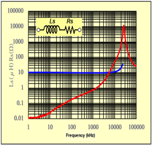
When an equivalent circuit of coils is represented as , the frequency characteristic of our power inductor (CER1277B-101) is as Graph-1. We can find almost same trend for the inductors made of ferrite core.
When supplying the current containing AC, it is necessary to consider the loss of AC(high frequency) as well as DC.
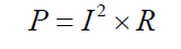
However the heat generation is proportional to the loss (= current squared). If the ratio of DC and AC is 10:1, the heat generation of DC and AC is calculated to be equal when the Rs is 100 times bigger.
If the heat generation is unexpectedly large, it may be necessary to check the current waveform supplying to the coil.
Specification of current value isn't fixed by wire size
In general, if a wire is used for wiring, larger current can be supplied to thicker wire. For wire-wound coils also, if the wire is thicker, DC resistance will decrease and the heat generation will become less. Therefore, larger current can be supplied to the coil.
However, the current which can be supplied to the coil is not uniquely fixed by thickness of a wire, like XX amperes (A) for XX mm wire.
It is because the current limit is fixed by heat generation by current supplied, instead of wire size.
Even though the wire is thin, the coil can endure large current despite it's appearance, if it has a structure letting out the heat.
For your reference, we created comparison table between our chip inductor (C2012B)and power inductor (7E06LB). As you can see from the values of Table-1, the wire size is three times different even though the allowable current value is the same. That is, the cross section area is nine times different.
| Type | Inductance | DC Resitance (mΩ)max. |
Temprature rise allowable current (mA) |
Wire diameter (mm) |
|---|---|---|---|---|
| C2012CB-15N | 15µH | 170 | 600 | 0.05 |
| 7E06LB-470 | 47µH | 610 | 610 | 0.12 |
Power inductors have a thick wire and the low allowable current value because the heat generated in coil is hard to be let out. We believe that the wire bonding of semiconductor is pretty thin even for high power application.
The temperature of coil varies depending on mounting method.
The heat generated from a coil can be categorized into two: first one is the heat which lets out through the air on the coil surface (air convection), second one is the heat which lets out from the connection of the coil (heat conduction).
Especially, the heat transferred from terminals to the printed wiring board varies depending on the land pattern size. So the temperature of coil will significantly change. Therefore, it is possible to decrease the temperature rising by releasing the heat by using effectively (=increase the size).
In addition, the airflow varies depending on the direction of the printed board – whether placed horizontally or vertically. Therefore, the heat generation of coil may vary.
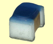
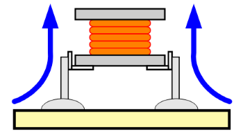
In an extreme case, if the coil is evaluated under tentative soldering as Figure-1 at the prototyping, the temperature may decrease more than the coil mounted on the board formally.
Author
- Some of the products listed in this document are no longer in production.
- As some time has passed since the article was written, the information provided may still contain outdated content.
If you have anything, you can send e-mail by clicking here.
Tips for COIL users Part-1
- (1) Differences between Coil and Inductor
- (2) Main parameters of the inductor
- (3) Inductance of the coil parameters
- (4) Temperature rising of inductor
- (5) What's Q
- (6) Self Resonance Frequency of Inductor
- (7) Open and close magnetic circuitr
- (8) Eddy current & Shield
- (9) Temperature and insulation characteristics
- (10) Operation of coil
- (11) Coupling of coil
- (12) Tips when you use a coil