
(3) Inductance of the coil parameters | Tips for COIL users(Part-1)
(3) Inductance of the coil parameters
This third topic is about "Inductance of coils". You might think that each topic is not linked that much, but we hope this could help your understanding of the coils.
Inductance of wound coils
In the first topic, the coils are described as the components with wire wound up in spiral. Then, the relationship between the inductance (L) of coils and the winding turns (N) is as below (The inductance is proportional to the square of winding turns (N)).
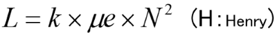
k :Constant value depending on a form and so on μe:Effective permeability
For the wound coils, when the winding turns become double, the inductance becomes quadruple. In the recent case of low inductance coils, if the winding turns changes 1T, the inductance will significantly change. Because their winding turns is small and must only be integer.
For example, the Table-1 shows each inductance per turns when the inductor has 5T and 4.7uH. In this case, we can't build the inductance with the center value of 10.0uH.
| WindingTurns(N) | Inductance (L) |
|---|---|
| 5T | 4.7µH |
| 6T | 6.8µH |
| 7T | 9.2µH |
| 8T | 12.0µH |
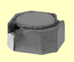
For other examples, the inductance is 6.8uH at 11Ts in the case of CER8042B (Photo-1).
Some engineers of set maker know the formula above, and may request like this: “Please decrease one turn to achieve inductance XXuH!”.
When developing inductors, we usually struggle and fix the forms to meet the turns and the inductance according to E6 or E12 series.
For the wound inductors, it is possible to set the customized inductance (by changing the turns). However, some cases can never be achieved depending on inductance value.
Effective permeability
Even though magnetic materials are added to an air core coil, the actual inductance won't increase in multiples of material permeability. This is because not all of the magnetic flux generated from the coil passes through the magnetic materials. Then there is a standard named effective permeability as the scaling factor of the actual inductance value from the air core coil.
If any air gaps exist in the magnetic circuits, the effective permeability will significantly decrease. For this reason, even though very high permeability material is used, the effective permeability will not so much increase.
Therefore, there is a limitation of the downsizing of inductor by using materials with high permeability.
Core Gap
All values of temperature rise allowable current were same concerning the 7G17D specification (Table-2) shown in the former issue. That's because the DC resistance was same. In fact if the DC resistance is same, the windings inside the coil are all the same.
| Type | Inductance (µH) |
DC saturation current(A) |
Temprature rise current(A) |
|---|---|---|---|
| 7G17D-100M | 10±20% | 26.0 | 8.2 |
| 7G17D-220M | 22±20% | 13.0 | 8.2 |
| 7G17D-330M | 33±20% | 7.5 | 8.2 |
Then, do you know how we can change the inductance? The answer is by changing μe (effective permeability) without changing the form or turns of inductors.
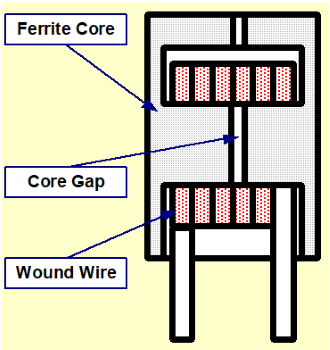
Actually we provide the gap (slit: Figure-1) to a part of ferrite core of the magnetic materials. The gap contributes to change the effective permeability (apparent magnetic characteristics) without changing the materials of ferrite core.
However, the gap size affects not only the inductance but also the DC saturation allowable current characteristics.
The relationship among the gap size, inductance, and DC saturation allowable current characteristic is as the Graph-1 below.
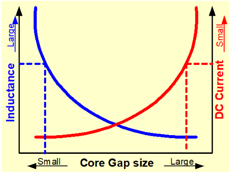
The gap size will be determined in view of both balances.
Please look at the Table-2 again. You can find the Table-2 is like the Graph-1. (If inductance is large the gap is small.)
"To decrease the loss, we have to decrease turns of wire for low resistance and narrow the gap for increasing inductance. But, the DC saturation allowable current characteristic will decrease… What a dilemma!"
Then, it is a good opportunity for us, coil manufacturer, to show our strength how the gap is designed and set at which part of the inductor to achieve the best characteristics.
Author
- Some of the products listed in this document are no longer in production.
- As some time has passed since the article was written, the information provided may still contain outdated content.
If you have anything, you can send e-mail by clicking here.
Tips for COIL users Part-1
- (1) Differences between Coil and Inductor
- (2) Main parameters of the inductor
- (3) Inductance of the coil parameters
- (4) Temperature rising of inductor
- (5) What's Q
- (6) Self Resonance Frequency of Inductor
- (7) Open and close magnetic circuitr
- (8) Eddy current & Shield
- (9) Temperature and insulation characteristics
- (10) Operation of coil
- (11) Coupling of coil
- (12) Tips when you use a coil