

Types of Noise Suppression Components | Helpful Trivia For Coil Users
Types of Noise Suppression Components
Capacitor Varistor Diode ・・・Inductor
Our company manufactures and sells board-mount (SMD/PIN) type inductor components.
| DC Line | Modes of noise | Key product categories | Main applicable frequency range |
|---|---|---|---|
| AV Equipment OA Equipment Digital home appliances White Goods Various power Module |
Differential mode | CER/CBE/CVESeries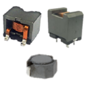
| Conducted Emission::150kHz~108MHz Radiated Emission:30MHz~ |
| PRCG4036C PRBG4029C PRBG4036C 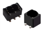 |
Radiated Emission: Hundreds of MHz ~ | ||
| Differential mode・Common mode | TDG5629C |
Radiated Emission:100MHz~ | |
| Common mode | TDG6029C |
Radiated Emission:100MHz~ | |
| TQR
/TGQR
/TJF Series (5~12mm) 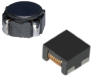 |
Conducted Emission:150kHz~108MHz Radiated Emission:30MHz~ |
Noise Filter Application Examples
① Class-D Audio(Single)
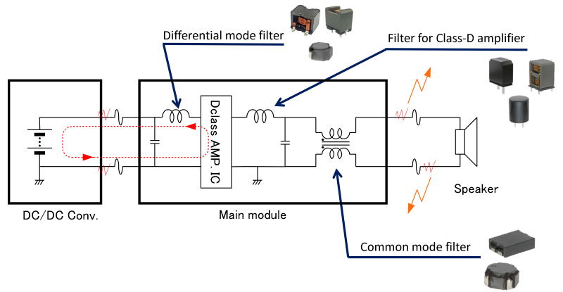
② Class-D Audio(BTL)
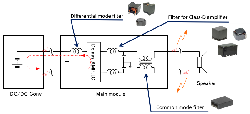
③ Electric mini vehicle
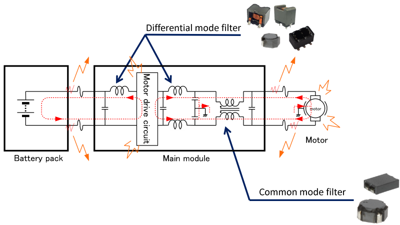
④ Electric mini vehicle
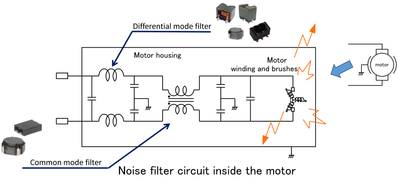
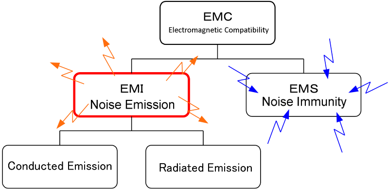
What is EMC?
EMC(Electromagnetic Compatibility)
The design and manufacturing conditions of equipment to ensure electromagnetic compatibility.
- Does not become a source of electromagnetic interference
- Is not affected by electromagnetic interference
- Continues to operate normally even when interference is present (ensures compatibility)
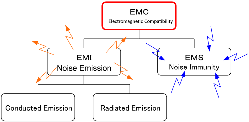
EMI(Electromagnetic Interference)
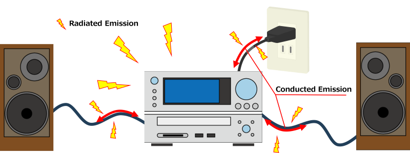
Emission: The release of unwanted electromagnetic noise from electrical equipment into its surroundings.
Conducted Emission and Radiated Emission
- Conducted Emission:Noise emitted through electrical wires or cables
- Radiated Emission:Noise emitted through space as electromagnetic waves
Noise Filtering
| AM | FM | DAB | TV | Mobile Wi-Fi | |||||||
| 3MHz | 30MHz | 100MHz | 200MHz | 1GHz | 2.5GHz | ||||||
|---|---|---|---|---|---|---|---|---|---|---|---|
| Filtering limit efficiently achieved using Mn-Zn cores |  |
General filtering limit using Ni-Zn core power inductors with low inductance |  |
Typical range where high impedance can be achieved with single-layer wound Ni-Zn core power inductors | |||||||
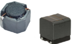 |
Common frequency range that can be filtered with power inductors | 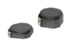 |
General limit achievable with large Ni-Zn core single-layer wound power inductors | 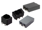 |
|||||||
Requirements for Noise Filter
- Impedance: The higher, the better
- SRF: The higher, the better
- Core Loss: The higher, the better
- DC resistance: The lower, the better
- Temperature Rise: The lower, the better
- Magnetic saturation: The higher, the better
- Temperature characteristics: It does not matter
※Generally large current or DC with low-frequency is applied.
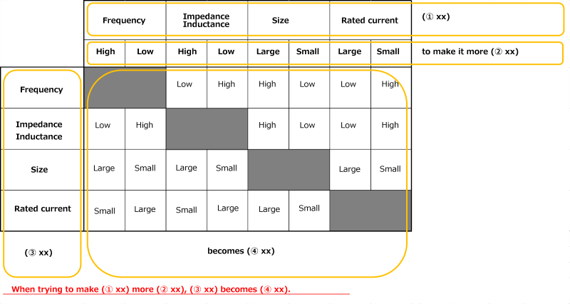
Trade-off Characteristics of Inductors
Author
Notes
- Some of the products listed in this document are no longer in production.
- As some time has passed since the article was written, the information provided may still contain outdated content.
If you have anything, you can send e-mail by clicking here.