
(11) Coupling of coil | Tips for COIL users(Part-1)
(11) Coupling of coil
The eleventh is about "coupling between coils". Let's see what is the condition of coupling when multiple coils are aligned.
Direction of magnetic flux
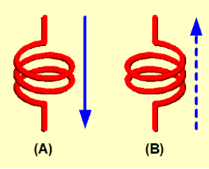
Direction of magnetic flux which is generated from a coil depends on a winding direction (right and left winding) and a current direction which flows through a coil (blue arrow).
Therefore, in the case of Figure-1 (A) and (B), the winding and the current directions go across each other. Therefore, the direction of magnetic flux is same.
Indication of inductor polarity
When two or more coils are placed, magnetic fluxes that are leaked from a coil may influence one another. Therefore, a polarity is marked as shown in Photo-1 depending on products.
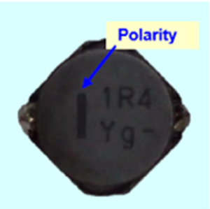
Normal coil has a "winding start" physically, however the winding direction is not always the same for all forms because of production method.
Originally the indication was used to show a coupling direction of coils with multiple windings like transformers. Normally, all winding direction is same. In addition, the direction of magnetic fluxes is leaked outside is not specified.
Then, such indication was used also for inductors. Therefore, physical "winding start" is indicated generally at the present day.
Originally, the indication should be in accordance with the electric characteristic like a polarity of electrolytic capacitor. However, as there is no industry standard for the indication of inductor polarity, we can't ensure the 100% compatibility. Therefore, both "winding start" and "winding direction" may be specified in a coil specification.
Placed two coils close together
Two inductors were aligned (Figure-3) and measured to confirm a coupling between coils.

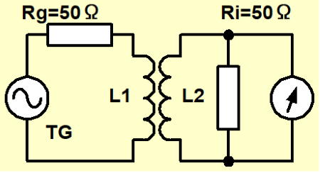
TG output of spectrum analyzer was added to an inductor (L1), and an output of the other inductor (L2) (= input power) was measured based on measurement circuit specified in Figure-2. At this time, TG output was set in order for input value to be 0dBm without inductors (L1 and L2).
Two individual coils being coupled is the same structure as transformer. Therefore, some power of either coil is transferred to the other coil. However, generated power is very small because the coupling is not so much as the transformer has.
Graph-1 shows a comparison between an unshielded SMD inductor (7A10N) and shielded one (7E08N) concerning coupling between coils.
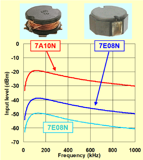
In the case of the unshielded inductor, input power decreases (=coupling is small) because not all leaked magnetic fluxes enter into the adjacent coil. In the case of the shielded inductor, the graph shows that the input power decreases about 20dB more than the unshielded one due to the effect of magnetic shield.
Then in the case that the shielded inductors are separated about 4mm (about half of dimension) and measured, it was confirmed that the input power decreased about 10dB(light blue).
You can find that the shielded inductor performs effectively when multiple coils are closely placed.
※7A10N,7E08N This product is not currently in the lineup.
2 in 1 Type
We have some types of 2 in 1 products among our class D amplifier coils. For those products, we achieved the reduction of mounting work by half and reduced the mounting area by putting two coils together.
When two coils are closely placed, coupling between coils is concerned. However, in fact, each coil has a large shield effect and coupling between coils is very small.
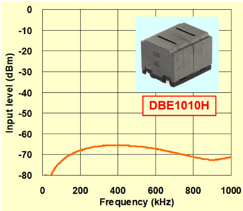
Graph-2 shows measurements of our DBE1010H, 2 in 1 type for class D amplifier. The coupling between coils is smaller than when the normal shielded coils are aligned.
High frequency
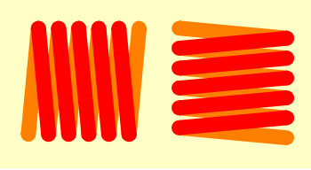
For high frequency circuit, air core coils and chip inductors are often used due to small inductance. When these coils are placed perpendicularly like Figure-4, magnetic flux from either coil is hard to go through the winding circle of the other coil. As the result, coupling of mutual coils is minimized.
Author
- Some of the products listed in this document are no longer in production.
- As some time has passed since the article was written, the information provided may still contain outdated content.
If you have anything, you can send e-mail by clicking here.
Tips for COIL users Part-1
- (1) Differences between Coil and Inductor
- (2) Main parameters of the inductor
- (3) Inductance of the coil parameters
- (4) Temperature rising of inductor
- (5) What's Q
- (6) Self Resonance Frequency of Inductor
- (7) Open and close magnetic circuitr
- (8) Eddy current & Shield
- (9) Temperature and insulation characteristics
- (10) Operation of coil
- (11) Coupling of coil
- (12) Tips when you use a coil